Sunday, January 29, 2012

Science Project : Solar Car

Everything is going green these days. I thought it might be a good idea to convert a regular radio controlled car into a solar powered car. This would mean hours of fun without the need to change the batteries and would also make a good school science project. Here is what you will need:
  • A radio controlled car
  • Appropriate Solar Panel
  • One diode
  • Soldering Iron
  • Screw driver
  • Wires for connection
The car: 
You can choose any radio controlled car. It would however be a good to idea to check the available solar panel first. I chose a car that uses 4x1.5V AA batteries. This would add up to 6V.

The Solar Panel:
Since the car requires 6V I bought a small 6 volt panel from eBay. 

The Project:
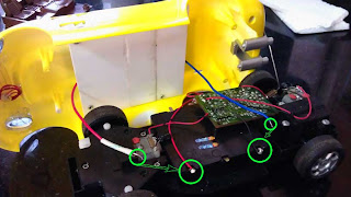
The first part involves taking the car apart. Most probably you would find the appropriate screws right below the car. The one I bought had four screws. Once these were unscrewed the top part could be easily taken off revealing the electronic circuit.
You will find two wires [ mostly red and black] coming out of the battery box. The red is the positive and the black is the negative wire. These are the two points that we will connect our solar line to. The car that I used had head lights which went on when the car moved. This was directly connected across the motor that drove the wheels. To save power I disconnected the head lights. 

Some radio controlled cars come with rechargeable batteries that are not AA or AAA but the connection would still remain the same. Our aim is to connect the output of the solar panel to the battery terminals.

The under carriage of the car houses the battery box , open it and replace the AA batteries with rechargeable AA batteries. Your car might come with non-rechargeable batteries like mine did. Make sure that you have rechargeable batteries in the box or this project wont work. I took off the seats and the wind shield to facilitate the fixing of the panel there. A piece of acrylic was cut out to cover the empty space and prevent dust and moister from directly falling on to the circuit below.

Cut two pieces of wire, red [+] and blue [-] and the same is soldered on to the + and - terminals of the panel. At the far end of the red [positive] wire the diode is soldered. The diode has a silver ring to denote the negative side of the diode and the other side is positive. The positive side of the diode is soldered on to the positive wire coming from the panel. 
The acrylic piece has screw holes drilled at the exact places where the seat fixture had screws. So the same screws were used to securely fasten the acrylic panel on to the car body. I then used rubber based glue to attach the panel to the body of the car. 

Make sure that that there are no batteries in the battery box while you do the following. The bare end of the red wire with the diode [ silver ring end] is soldered to the positive terminal of the battery box and the blue wire to the negative side. It would be good to recheck the connection before popping the batteries back in.

Explanation for the School Science Project:
A photo voltaic cell converts the light from the sun into electricity. The panel mounted on the car produces electricity that charges the on board battery bank. The diode is a component that lets current flow only in one direction. When the panel is not producing current there is a possibly for the power from the battery to drain out into the panel. The diode is kept to prevent the reverse flow of current from the battery into the panel. We could say that this is a very simple charge controller. In larger electric cars that are seen on the street, a more sophisticated charge controller is used to control the charging of the battery in the car. The components in any solar car would be the, solar panel > charge controller > battery. The rest of the circuitry would control the motor drive. This same technology one scaled up can be used to build bigger solar powered cars.

Friday, January 6, 2012

Computer UPS Hack / Extended Capacity UPS Build

There is a room on my terrace that I use for my hobby projects and fun research. When the room was build a year back I had given a provision for a separate inverter connection for the room, isolated from the rest of the house. I hadn't fixed one as the need never arose. Of late there has been quite a few intermittent power outages and I decided that it was time to fix one. As I had a functional spare inverter lying around, it was the first choice. So I decided to get myself a new battery and hook this up.The power outages normally last from 10 min to 1 hour.

Shift to the UPS:
I have a few electronic test equipment which are sensitive to the power fluctuation, and so is the computer in the room. So I decided that the regular inverter was not a great idea. The next option was a UPS. Considering the load in the room a 600VA power source would suffice and I decided to buy one. A day passed and something struck me, it occurred to me that the computer UPS that I used in the room for my PC was a 600VA UPS. The internal battery was however a 7 AH 12V battery which drove a 300 watt computer for approximately 15 min. So if I bought a computer UPS and swapped the battery with a higher capacity external battery it would be perfect for my use.


Charging and stuff:
The AH reading on any battery stands for the 'Ampere Hour'. If a battery is rated 12V 7AH it would mean that if you draw 7 ampere from the battery it would last for one hour until it is discharged. Like wise if you draw 3.5 ampere it would last 2 hours and so on. To charge a battery efficiently you have to give it 10% of its current rating. So since we have 7 AH on our 12 volt battery the charger will be designed to charge it at .7 ampere [ 700 milli amps]. The important point to note here is that, if we connect a lower capacity battery [less that 7AH] the battery will heat up while charging and will eventually die faster than its life span. If we however connect a higher capacity batter all that would happen is that it will take proportionality longer to charge.

List of items required:
  • A 600VA computer UPS 
  • 12V DC computer fan 
  • Drill for drilling vent holes
  • 2 x High gauge wires and terminals
  • 26 AH SMF Battery 
On with the build:
When we use a higher capacity battery the UPS will run longer and so it is a good idea to fit a cooling fan. Since we use an external battery we remove the internal battery from the UPS ; this provides us ample space for the fan. I drilled some holes under the UPS and placed the fan in such a way that the air gets sucked in from below and goes out through the side and top of the company cut vent holes.The 12V fan was connected in parallel to the battery and is always on and continuously cools the ups. It draws very little power and barely adds to the load. 

The battery I selected was an Exide 26 AH sealed maintenance free [ SMF] battery that needs no attending to what so ever. This would give us approximately 4 times the backup of a computer UPS. The computer draws 300~400 watts of power and lasts 15 minutes on the built in 7AH battery and we have replaced it with a 26 Ah battery. A regular25 watt cfl light consumes  25 watts of power and a fan consumes about 50 watts if it is very efficient. So assuming that the computer has been shut down, [ I have a second ups connected to the computer which gives me ample time to shut down without taking any load from the extended UPS] the average load in the room would be around 100 watts if there are 2 x 25 watt cfl and the fan running.

This would mean that I should easily get 1~2 hours on the new setup which is more than enough. For extending the wire from the UPS, wires of the same gauge should be used and connected securely or there is chance for loose contact.  

I have had the system running for over a week now and so far it has worked well and switches perfectly. Since it is a UPS the electronic devices don't reset when the power goes off and comes back. 

Cost of the project:
600 VA Wipro UPS - Rs.1,500 [ Bought it from a friends shop and he took back the inbuilt battery and gave me the UPS for Rs.1000]
26 AH Exide Battery - Rs.2,300
Wires and miscellaneous - Rs.200
Total cost of the project: 1000+2300+200 =  Rs.3,500

The final outcome
p.s: The extra length of wire is for future upgrade.